NSL Galaxy Fiber Optic System Installation Instructions
One of the most exciting Architectural Lighting Systems Sold
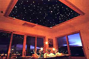
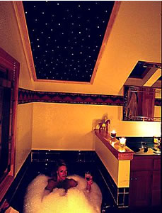
Create Stunning Fiber Optic Ceiling Panels
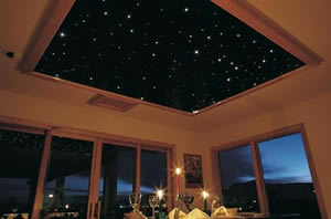
Fiber Optic Star Ceiling Kit through Gloss Black Acrylic Panels create a star ceiling for this restaurant.
How to Install & Operate the NSL Galaxy Fiber Optic System
The following instructions are provided to assure safe Installation: and operation of the Galaxy Fiber Optic System. Please read carefully before installing any part of or plugging in the Galaxy Fiber Optic System.
• The Galaxy Fiber Optic illuminators are presently Engineer Testing Laboratory (ETL) listed for indoor use only ("dry locations").
• Caution: Risk of Fire/Injury to Persons! Illuminator should be mounted in a well ventilated location and should have a 1" clearance on 5 sides. Do not cover with insulation.
• Caution: Risk of Fire/Injury to Persons! Turn off or unplug to change bulb!
• Caution: Risk of Fire/Injury to Persons! Use only a Halogen MR-11 of 35 watts for the GP-35B replacement. Use only a MR-16 of 50 watts for the GP-50 replacement. Use only a Halogen MR-16 of 75 watts for the GP-75 replacement. Make sure bulb has cooled sufficiently before removing. Do not touch bulb when removing/replacing. Use gloves.
• Plug into 120VAC, 60 hz only!
• Due to light output loss along the fiber, we do not recommend 1.0mm fiber in excess of 12 feet.
• All fiber optic applications work best in low ambient light environments.
• These products may represent a possible shock hazard or fire hazard if improperly installed or attached in any way. Products should be installed in accordance with the owner's manual, current local codes, and/or the current National Electrical Code (NEC).
System Description
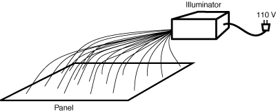
The Galaxy Fiber Optic System is comprised of three parts: the illuminator, the harness/fibers and the ceiling panel. Please see diagrams below. All illuminators include 1.0mm fibers for the use as star points in ceiling panels.
Fiber
All 1.0mm fibers are solid core consisting entirely of one acrylic material. All come installed in a fiber optic harness. If you wish to cut the material, you may do so with a good pair of garden shears.
Illuminators
| National Specialty Lighting Fiberoptic Illuminators | |||
|---|---|---|---|
| Illuminator | GP-35B-12' | GP-50-12' | GP-75-12' |
| Fiber Length | 12' | 12' | 12' |
| # of Fibers | 160 | 300 | 400 |
| Maximum panels | 3 | 4 | 4 |
| Area | 24 sq. ft. | 32 sq. ft. | 32 sq. ft. |
| Fibers per sq. ft. | 6.7 | 9.4 | 12.5 |
Caution: Risk of Fire/Injury to Persons! Illuminator should be mounted in a well ventilated location and should have a 1" clearance on 5 sides. Do not bury or cover with insulation
All illuminators have four rubber "feet" which you may simply rest the product on a mounting surface making note of the caution above. If you wish to suspend the illuminator from its top or sides, there are two mounting brackets included. Install in a suspended manner per the diagram below:
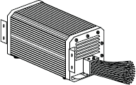
Fiber Harness
All 1.0mm fibers ship installed in a harness. The harness simply screws to the front of the illuminator per the diagram above. Installation: of harness should occur after you have positioned both illuminator and installed fibers into pre-drilled ceiling panel holes.
Ceiling Panels
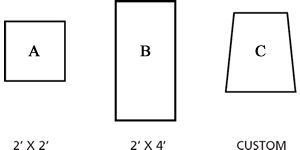
The Galaxy Fiber Optic System is composed of the three different sizes of ceiling panels shown below.
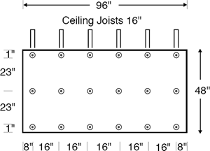
A For use in a 2' x 2' drop ceiling. Pre-drilled with a minimum of 25 holes.
B For use in a 2' x 4' drop ceiling. Pre-drilled with a minimum of 50 holes.
C For use in custom dimensioned application. Can be shipped as large as a 6' x 8' dimensions. Larger panels require mounting screws as shown under "Custom Panels" below. Pre-drilled with at least 5 holes per square foot.
Installing Standard Panels
The system will consist of the illuminator, the fibers and harness and the 2' x 2' or 2' x 4' panels.
Installation: steps are as follows:
1 . Separate fiber harness from illuminator. Place illuminator in final mounting position assuring availability of 110V power, ventilation and illuminator is within minimum run of fibers to all ceiling panels (you will need at least 12" above the ceiling panels).
2. The illuminator comes with both a color wheel and a black and white "twinkle" wheel. The black and white "twinkle" wheel is installed in every illuminator. The wheel motor and cooling fan runs constantly when illuminator is plugged in. If you wish to have the "star points" change color all you need to do is unplug the light source, remove the front cover, unscrew the center bolt on the "twinkle" wheel, install the color wheel and re-screw the center screw bolt until snug.
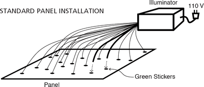
3. The easiest way to complete the next step is to first mount the panel, green dots up, in place. The 2' x 2' panels have a minimum of 25 pre-drilled holes; 2' x 4' panels have a minimum of 50 pre-drilled holes.
All of the fibers are 1 millimeter. Holes in the ceilings panels are drilled through the green stickers. Some holes are drilled at a slight angle to vary light intensity and dynamics as you view the panel from different places in the room.
Push fibers into pre-drilled holes until about 2" past other side of panel.
One GP-35B-12' can power up to (6) 2' x 2' or (3) 2' x 4' panels at 6.7 fibers/sq. ft. One GP-50- 12' can power up to (8) 2' x 2' or (4) 2' x 4' panels at 9.4 fibers/sq. ft. One GP-75-12' can power up to (8) 2' x 2' or (4) 2' x 4' at 12.5 fibers/sq. ft.
4. Plug light source in and assure all "star point" fibers work.
5. From the viewing (room) side of the panel, push all fibers up so that ends are flush with panel.
Installing Custom Panels
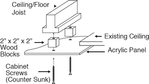
This system also will consist of the illuminator and fibers and harness and the custom panel(s). Custom panels over 8 square feet (2' x 4') will not work well in a drop ceiling due to the weight and the "sag," of the panel. Almost all custom panels are mounted to Floor or ceiling joists per diagram below.
Measure and drill countersunk mounting holes through viewing side of panel. Install illuminator per "Standard Panels," #1.
Place custom panel on saw horses below final mounting area, green dots toward ceiling. Install fibers by pushing ends at least 2" into all holes on custom panel.
Lift custom panel and fiber harness up into final mounting area and screw panel into ceiling/Floor joist through 2" wood spacers. Attach fiber harness to illuminator and push fiber ends flush with bottom of panel.
Trim the edge of the custom panel as necessary.