Installation Steps
Invisible Trim
Remodel Housing
IMPORTANT: NEVER attempt any work without shutting off the electricity.
- Read all instructions before installing.
- For installation by a qualified electrician.
- System is intended for installation in accordance with National Electric Code, and local regulations.
- Consult with local inspector to assure compliance.
- To reduce the risk of fire, electrical shock and injuries to persons, turn off power at main switch before installing or modifying the system.
- Warning: (Risk of fire) do not install insulation within 3" of fixture sides, or junction box, or in a manner to entrap heat.
- Retain instructions for future maintenance reference.
OVERVIEW
Housing is remodeling type, 11 watts maximum. Housing requires an Invisible Trim™ from the appropriate series.
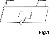
1. Cut out a hole 5"in the drywall (as Fig.1).
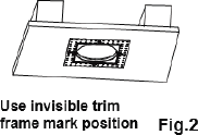
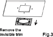
2. Raise Invisible Trim™ frame to ceiling opening as a template to mark position of countersinks for plastic anchors installation (as Fig.2 and Fig.3).
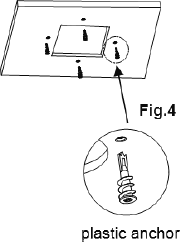
Install plastic anchors to ceiling (as Fig.4).
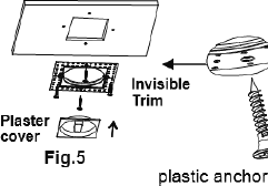
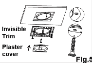
3. Raise Invisible Trim™ frame to ceiling opening and secure with screws supplied (as Fig.5).
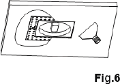
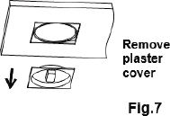
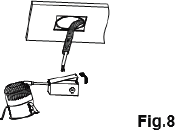
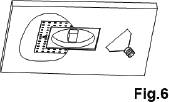
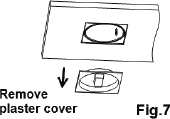
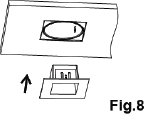
4. Apply plaster or spackle over Invisible Trim and sand surface when dry for a finished look (as Fig.6). Remove plaster cover (as Fig.7). Pull ceiling wire through the hole (as Fig.8).
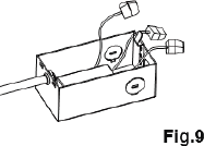
5. Remove junction box door and connect fixture wires to building wires, insert each supply wire into appropriate junction box connector. Connect black fixture wire to hot, white fixture wire to neutral and green fixture wire to ground (as Fig.9).
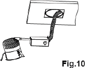
6. Place all wiring and connectors back in wiring box and replace junction box door (as Fig.10).
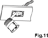
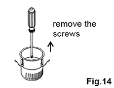
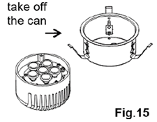
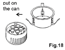
7. Pivot the J box up through the hole, followed by the can (as Fig.11).
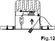
8. Raise the housing in the Invisible Trim and push the springs outward from inside the can (as Fig.12).
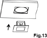
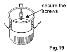
9. Push the Invisible Trim assembly up until the Invisible Trim is flush to the ceiling (as Fig.13).
Installation Steps
Invisible Trim
New Construction Housing
IMPORTANT: NEVER attempt any work without shutting off the electricity.
- Read all instructions before installing.
- For installation by a qualified electrician.
- System is intended for installation in accordance with National Electric Code, and local regulations.
- Consult with local inspector to assure compliance.
- To reduce the risk of fire, electrical shock and injuries to persons, turn off power at main switch before installing or modifying the system.
- Warning: (Risk of fire) do not install insulation within 3" of fixture sides, or junction box, or in a manner to entrap heat.
- Retain instructions for future maintenance reference.
OVERVIEW
Housing is new construction type, 11 watts maximum. Housing requires an Invisible Trim™ from the appropriate series.
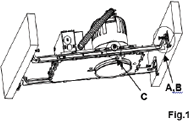
1. Install mounting frame using two hanger bars (24.5" max).
Bars are notched on the ends to fit over "T"bars in suspended ceilings.
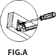
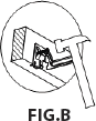
Hanger bars include a captive mounting "screw-nail"for ease of installation (as Fig.1). Align the bottom of the hanger bar with the bottom of the wood joist. Secure the "screw-nail"on each end by screwdriver (as Fig.A), or by hammer (as Fig.B).
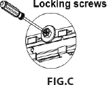
2. Slide fixture along bar hangers into desired location.
Use locking screws to secure (as Fig.C).
3. Junction box is suitable for branch wiring and has trade size knockouts and integral non-metallic sheathed cable connectors.
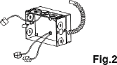
4. Remove spring latched junction box door and connect fixture wires to building wires and insert each supply wire into appropriate junction box connector. Connect black fixture wire to hot, white fixture wire to neutral and green fixture wire to ground (as Fig.2).
5. Place all wiring and connectors back in wiring box and replace junction box door.
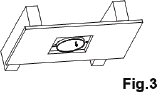
6. When installing in drywall, cut a hole 6.125" in the drywall (as Fig.3).
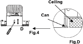
After installing drywall, if necessary, adjust fixture for ceiling thickness by loosening hex screws that attach the round housing to the plaster frame (as Fig.4).
7. Raise Invisible Trim™ frame to ceiling opening and secure with screws supplied (as Fig.5).
8. Apply plaster or spackle over Invisible Trim™ and sand surface when dry for a finished look (as Fig.6). Remove plaster cover (as Fig.7).
9. Push the trim assembly up until the trim ring is flush to the ceiling (as Fig.8).